Nicholas Lazo

mechanical engineering — b.s. expected 2027

I design and build aerospace structures at Florida International University, where I lead engineering on an AIAA Design/Build/Fly aircraft. I machine and lay up most of what I draw.

Projects

Design work I owned end to end, from requirements through fabrication.

AIAA Design/Build/Fly aircraft

An aircraft that deploys, tows and retracts a sensor in flight. I'm Chief Engineer: four team leads, roughly 30 active members, and the technical calls. In preliminary design.
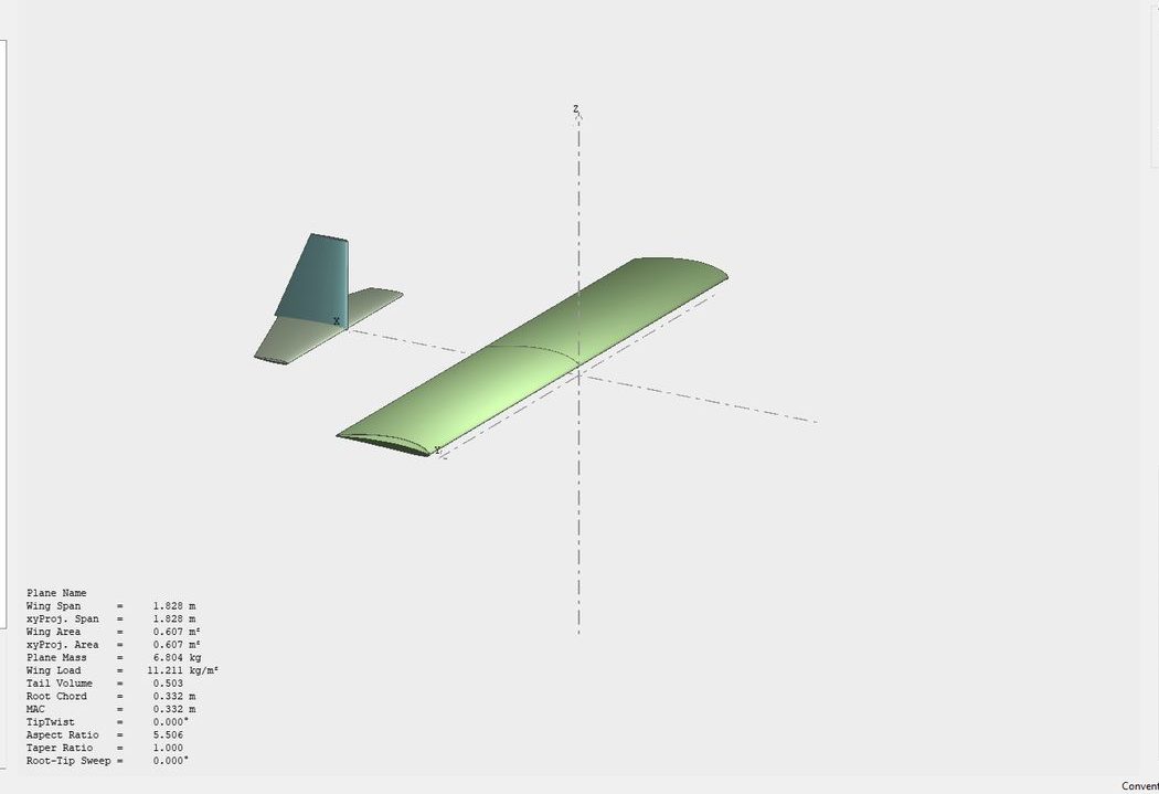
XFLR5 plane analysis: three-dimensional view of a high-wing candidate with conventional tail, and a geometry readout listing span, wing area, mass, wing loading and aspect ratio.
XFLR5 — a candidate configuration: 1.83 m span, AR 5.5, NACA 4412
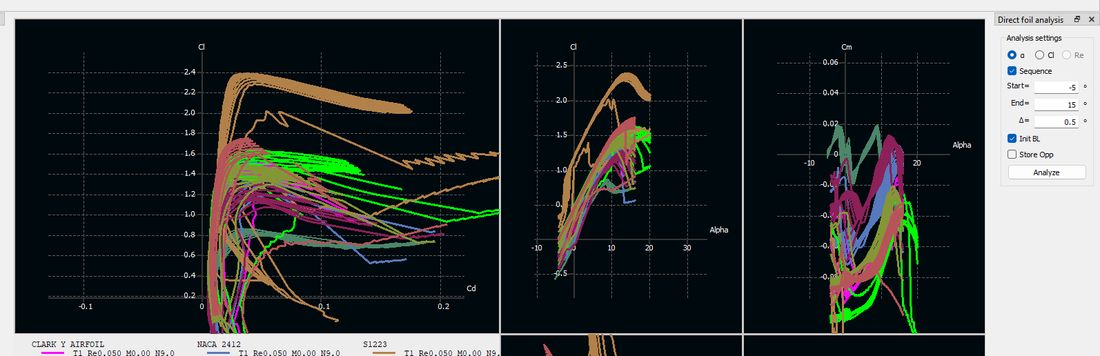
XFLR5 direct foil analysis showing lift, drag and moment polars for eight airfoils swept across Reynolds numbers.
Airfoil comparison across Reynolds numbers — Clark Y, NACA 2412, 4412 and 0009, S1223, SD-series
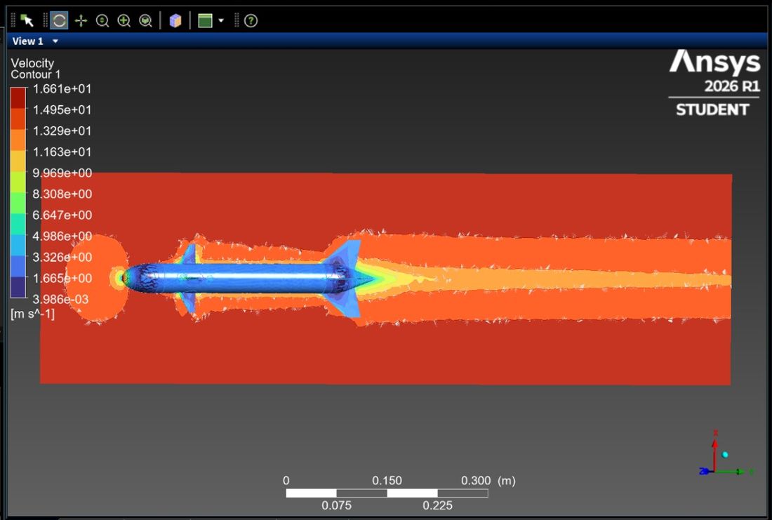
Ansys Fluent velocity contour around the towed sensor body, showing the wake extending downstream.
Ansys Fluent — velocity field around the towed sensor
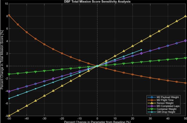
Line chart of percent change in total mission score against percent change in each design parameter, with six parameters plotted.
Mission score sensitivity — sensor weight dominates, flight time second
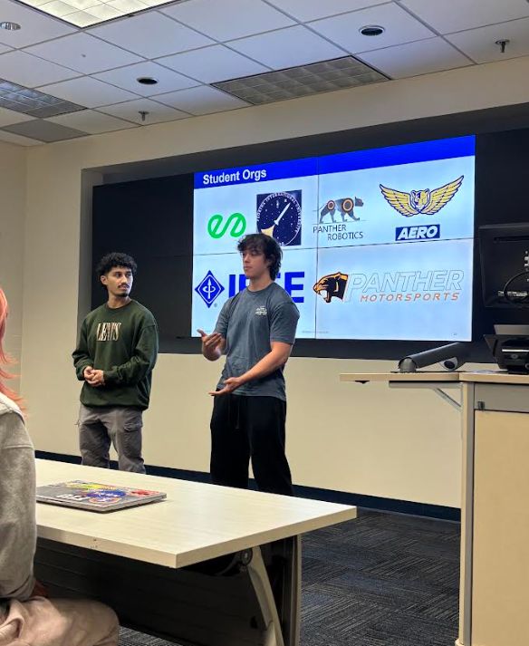
Speaking to a room alongside the club president, with a slide listing FIU student engineering organisations on screen behind.
Speaking with the club president at a recruitment event, ~60 attendees

The mission

The aircraft has to deploy a sensor mid-flight, tow it, and retract it. A towed body on a line changes the whole configuration problem, because the airframe is sized around a system that leaves it and comes back.

What I do

I lead four sub-teams and hold them to schedule, but the job that matters is owning the decisions that cross those boundaries. Most of my own work is the analysis behind them: configuration trades in XFLR5 — tail layout, wing position, span and aspect ratio — and airfoil selection across Reynolds numbers, each run as a polar rather than argued about in a meeting.

Where the score comes from

I ran a sensitivity study on the competition's scoring equation. Sensor weight moves the score more than any other parameter, with M2 flight time second — halving sensor weight is worth roughly 8% of total score, where most parameters return a fraction of that. That's where the team's hours go. I've also started taking the towed body into Ansys Fluent, though I'm a beginner there and treat it as directional.

Competition
AIAA Design/Build/Fly
Mission
Deploy, tow and retract a sensor in flight
My role
Chief Engineer
Team
4 sub-team leads, ~30 active members
Sub-teams
Aerodynamics, systems, avionics, manufacturing
Tools
XFLR5, Ansys Fluent, SolidWorks
Status
Preliminary design and analysis
Coastal surveillance UAV

A 3D-printed fixed-wing aircraft built to scan coastlines. Version 1, flown as a proof of concept. Four engineers; I owned the CAD, the avionics and the machined hardware.

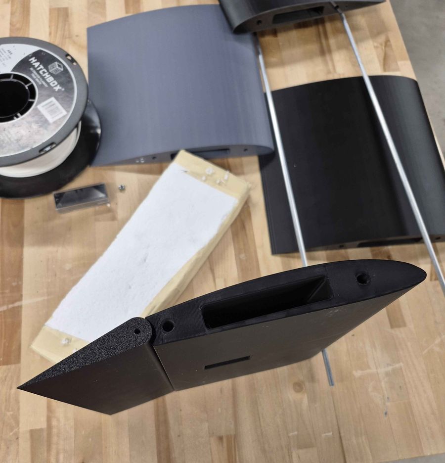
Printed wing sections, carbon spar rods, a foam core wing and a spool of ABS filament laid out on a workbench.
Printed sections, spars and foam core
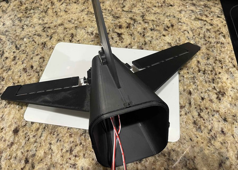
Rear view of the aircraft showing the tail surfaces, control horns and the servo wiring running forward through the fuselage.
Empennage and servo runs, wiring exposed
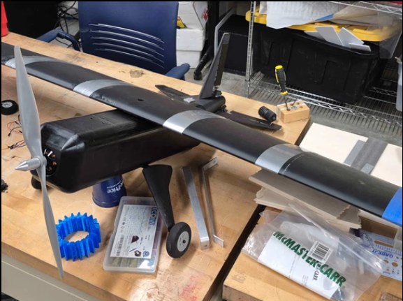
Completed aircraft on a bench with propeller, landing gear and tail fitted.
Complete airframe
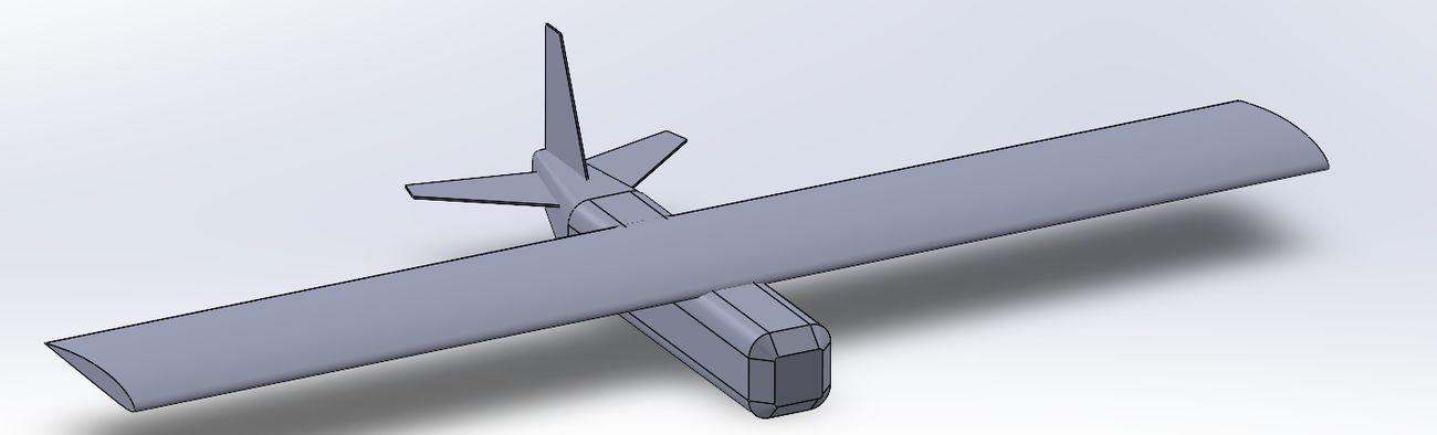
SolidWorks isometric render of the complete UAV: high-wing layout, boxed fuselage and cruciform tail.
SolidWorks model — high-wing layout with the electronics bay in the fuselage

Designing around the hardware

Modelled in SolidWorks with the electronics in the assembly from the first sketch, not fitted into leftover space later. Motor mount, battery, receiver and wiring routes all had places to live before the geometry was frozen — which is what makes a printed airframe practical, since reprinting a fuselage to make room for a component is an expensive way to learn.

What I did

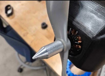
The CAD, and the full avionics install: every wiring run, receiver connection and control linkage. I also machined the prop nut ahead of the motor — a small part, but it sits on the one rotating assembly where a loose fit ends the flight.

What it taught

The airframe has a bay for the survey sensor, but we flew it empty on purpose; putting an expensive payload on a first article you aren't confident in is how you lose both. V1 did not achieve flight. Building it taught me where a printed structure is heavy for what it carries, and how fast weight accumulates once every bracket is real — which I took straight into the DBF aircraft, where weight is scored. V2 is on hold while that runs.

Mission
Coastline scanning and surveillance
Team
4 engineers
My role
CAD, avionics integration, machined hardware
Build
3D-printed airframe
Tools
SolidWorks, lathe, 3D printing
Status
V1 built and proven
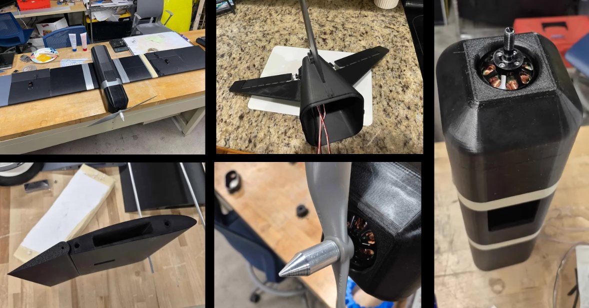
Five build photos: printed parts on a workbench, rear view showing internal wiring, the motor mount with the brushless motor installed, a printed wing section, and the propeller with the machined spinner nut.
Build sequence — printed sections, wiring, motor mount, and the machined prop nut on the spinner

Boeing 787 maintenance platform

An OSHA-compliant rolling platform giving technicians safe working access to both the nose and the sides of a wide-body airframe. Designed it, led the team, presented it to a panel of Boeing engineers.

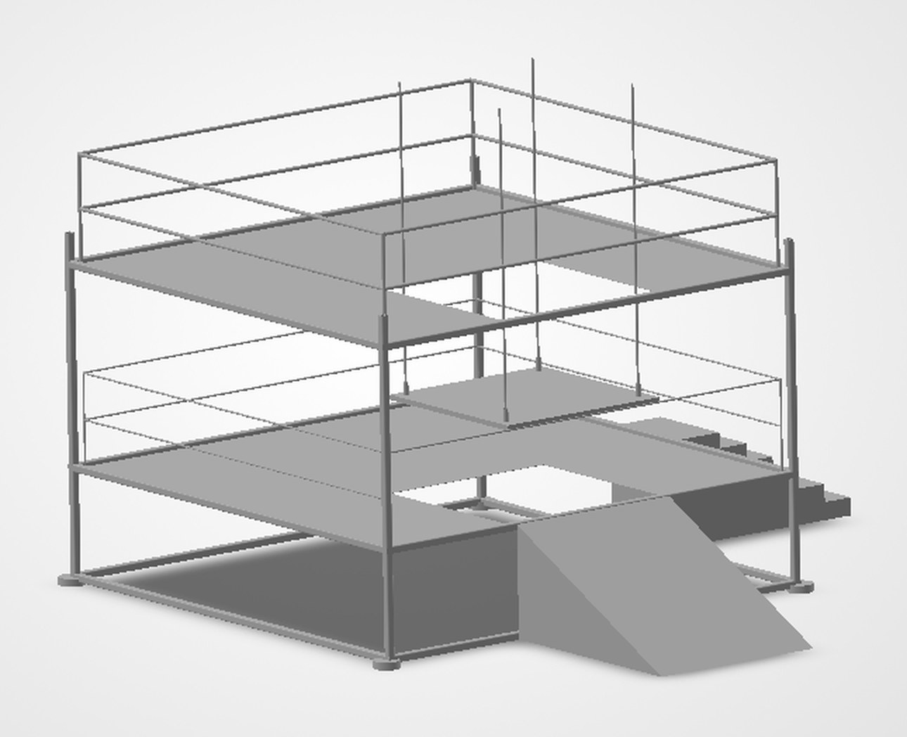
Isometric SolidWorks render of the two-level maintenance platform, showing guardrailed upper and lower decks, a switchback access ramp, a stair run, and a cutout in the lower deck that wraps the fuselage.
Two-level deck with switchback ramp and fuselage cutout SolidWorks · iso
Aircraft
Boeing 787
Team
4 engineers, led by me
My role
Team lead, sole designer, primary presenter
Tools
SolidWorks
Standard
OSHA compliant
Result
2nd place — judged by Boeing engineers

The problem

The nose and the sides of a 787 sit at very different heights, which drove the architecture: a lower deck for side access, an upper deck at nose height, and a switchback ramp so nobody carrying tools climbs a ladder. Guardrails, toeboards and deck grading were dimensioned to OSHA from the first sketch, not added at review.

What I spent the time on

The cutout in the lower deck. It has to sit close enough that nobody is overreaching, with enough standoff that neither the structure nor a tool in someone's hand touches the skin. Mass traded against mobility the same way — stiff underfoot, still repositionable by hand on locking casters. Pneumatic and electrical runs go inside the deck rather than across it.

The review

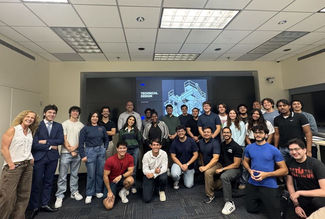
I presented to a panel of practicing Boeing engineers who critiqued the design directly. It placed 2nd.

All competition participants and judges gathered in the presentation room, with a technical design slide showing the platform on screen behind them.
Everyone who competed, at the end of presentations — the platform on screen behind

Machine shop

I make the parts I draw. Most of my design decisions come from knowing what a mill can actually hold.

Machined aluminium prop nut and spinner cone installed on the propeller shaft ahead of the motor.
Turned aluminium prop nut — Coastal UAV, installed
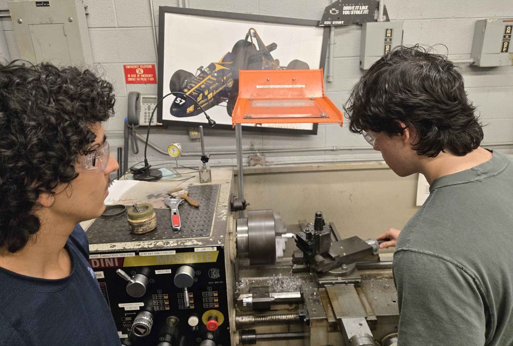
Two students at a manual engine lathe, one operating the cross slide while cutting a small part.
Turning on the manual lathe
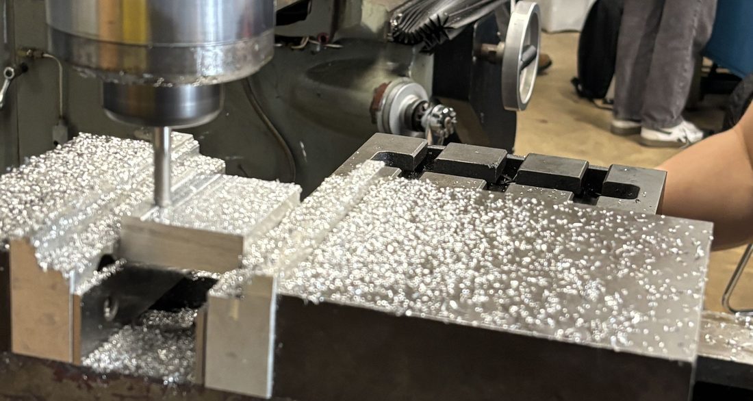
Aluminum stock clamped in a vise on a knee mill, endmill mid-cut with chips across the workpiece.
Knee mill — aluminum in the vise, endmill mid-pass
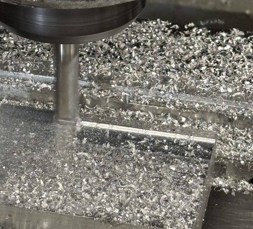
Close-up of an endmill cutting a step into aluminum, chips covering the surface.
Stepped pocket, roughing pass
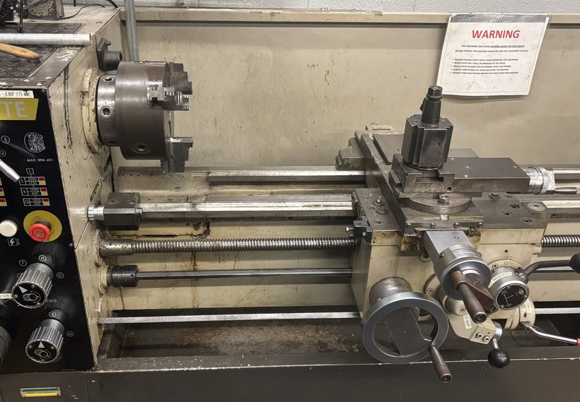
Nardini Mascote manual engine lathe with three-jaw chuck and tool post.
Nardini Mascote — turning and threading
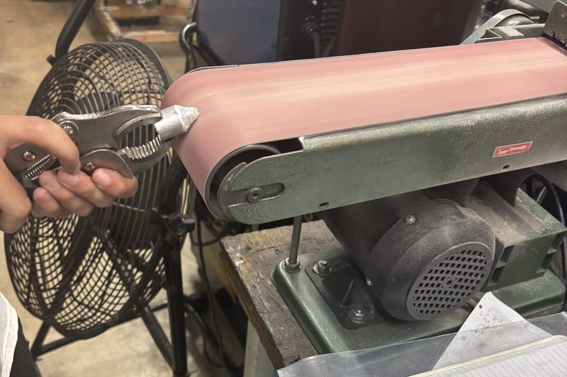
Deburring a small welded part on a belt sander.
Finishing and deburring

Manual milling

Squaring stock, pockets, steps, slots, bored and reamed holes. Comfortable working from a print and setting up my own workholding.

Turning

Facing, OD and ID turning, drilling, boring, threading, parting. Indexable and HSS tooling, ground as needed.

CNC

CNC milling and Mastercam toolpathing. Enough to program and prove out a part, and enough to know when a feature isn't worth the setup.

Design for manufacturing

Why the shop time matters. I catch the fillet that can't be cut and the setup that doubles the cost before anything reaches a machine. Also 3D printing for fixtures and prototypes.

Carbon fiber

Wet layup over foam cores for aircraft structure — from cutting plies to a finished part.

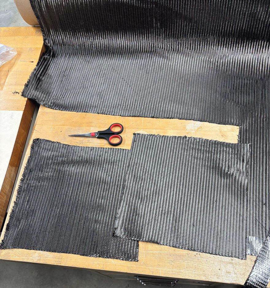
Carbon fiber twill cloth rolled out on a bench with plies cut to shape and a pair of scissors.
Plies cut to shape from the roll
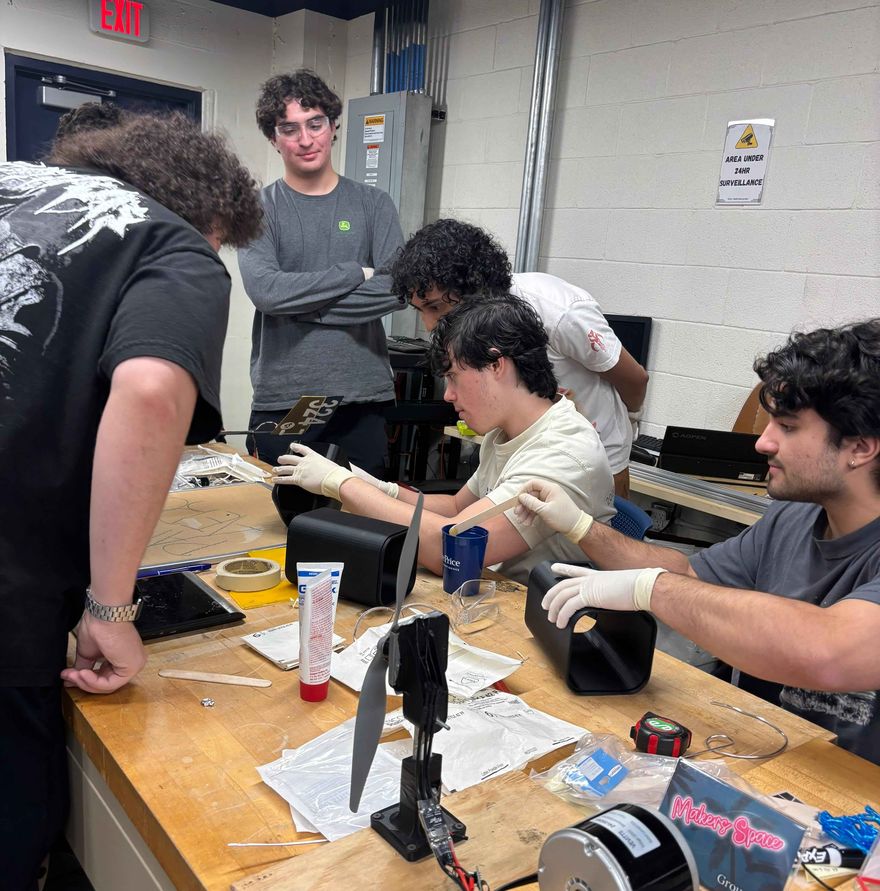
Team working at a bench with gloves, epoxy and spreaders during a layup session.
Wetting out — gloves, epoxy, working time
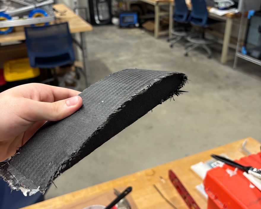
Finished carbon fiber skinned wing section held in hand, showing the weave over the foam core and the trimmed edge.
Cured skin over a foam core

Cutting and orientation

Plies cut from the roll to the shape the part needs, with fibre direction chosen for the load rather than for whatever nests best on the cloth.

Wet layup

Mixing resin to ratio, wetting out by hand, and working inside the pot life. Too little resin starves the laminate, too much just adds weight — on an aircraft, both are failures.

Cores and finishing

Skinning foam cores for sections that are stiff for their weight, then trimming, sanding and prepping surfaces for bonding into the assembly.

About


What pulled me into engineering is the point where a design stops being a drawing. Anything looks fine in CAD; it's contact with a real machine, real tolerances and a real weight budget that tells you whether you actually understood the problem. I'd rather find that out early than defend a model that was never going to work.

I tutor SAT math at Peace of Pi and lead the content team there. It's a lot of hours on top of everything else, but watching a student's score climb a hundred points because of something I explained is the most directly rewarding thing I do — and having to explain something clearly is the fastest way I know to find the gaps in my own understanding.

Outside that I train most days. It's a useful counterweight to work that otherwise lives entirely on a screen.

Fun fact: I have a full flight simulator rig at home. It's where my interest in aircraft started, long before any of it became coursework.

Resume


Nicholas Lazo

B.S. Mechanical Engineering — Florida International University

3.92cumulative gpa / 4.0

Looking for an aerospace engineering internship.

Available for any term. If you're hiring interns who can take a design from requirements to a machined, laid-up part, I'd like to talk.